Remote Weather Data Logger
June 16th, 2012
Projects
The goal is to make a remote data logger capable of continously collecting environmental data for at least a year.
project requirements
- self sustained - no external tethered power source allowed
- collected data will include time, sun luminance, humidity, temperature, and barometric pressure
- 24h data collection
- data will be logged to a SD card
- average microcontroller current should be <1mA
- As many surface mount components as possible (ideally all SMT)
basic circuit outline
Power from a bank of solar cells will be fed into a LDO linear regulator and then into a single cell lithium ion charger. A second regulator will regulate power from the lithium ion cell for the AVR, which will periodically log data into a SD card.
component selection
Availability was the biggest factor when I chose these parts. Digikey, Mouser, and Farnell were out of the question because of the high postage rates, but luckily many parts were available locally.
A SMPS boost/buck IC designed for energy harvesting would be ideal. Linear Technology does lots of power management stuff, so I started there. The LT3652 is close to perfect, but the input voltage range (4.95+) is too restrictive. The cells will go below that voltage when it is cloudy, and at voltages below ~10V, the efficiency of the IC drops down to 50%.
revision A schematic
The first revision uses 1206 and 0805 SMT components.
remote_weather_logger_rev_A.pdf
remote_weather_logger_revA_top.pdf
remote_weather_logger_revA_bottom.pdf
SD
Finding and implementing a SD card library was by far the hardest part of this project. The ‘standard’ library recommended by the members on avrfreaks.com is FatFS by elm-chan, which has pretty much everything you’d ever need. However, the compiled code for the avr example alone is over 64 kilobytes, more than four times what I have on the mega168. I tried reducing the code size by removing functions I did not need (reading, LFNs, and directory access), but it was still way over the limit.
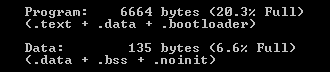
Luckily, elm-chan has another SD library specific for low memory micros. With only read and write capability, PetitFS is a slimmed down version of FatFS that compiles down to 6600 bytes. It is also more efficient with its ram usage, which I have precious little of on the mega168.
SD cards can be accessed with two primary protocols: the proprietary SD bus (which there are actually two versions of) and the serial peripheral interface bus. The SD bus is what all modern consumer devices use now. It allows for very high transfer speeds, but the protocol is so secret that a NDA has to be signed before the specifications can be released. The mega168 has a dedicated hardware SPI controller, and since the SPI protocol is well documented, it was a easy decision to go with SPI.
PetitFS requires the target SD card to be formatted with the FAT system. File systems are organized into clusters and sectors. Clusters (or allocation units in windows terminology) are groups of 512-byte sectors. The very common NTFS format for computer hard drives uses 4096-byte cluster sizes, with eight sectors in each cluster. A file cannot never be smaller than the cluster size. If you try and create a .txt file with a single letter saved (one byte) on a NTFS formatted hard drive, the ‘size-on-disk’ size will be one cluster, or 4096 bytes. This sounds counterintuitive, but by organizing sectors into clusters, there are a lot less memory addresses to handle.
Despite the advantages of organizing sectors into clusters, I won’t be able to use it for this project. Clusters can only be appended by holding the original data in ram, adding whatever data to it, then rewriting it completely, and with a paltry 1024 bytes of ram on the mega168, the absolute largest cluster size I can use is 512 bytes (so effectively sectors and clusters are equivalent). This leaves 512 more bytes of ram for system reserves and program variables.
sensors
tmp102
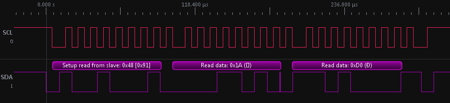
I2C bus diagram for a slave-transmit operation on the TMP102. The first byte (0x91) contains the device address (0x48) and the read-write direction. The temperature is stored in two eight-bit registers, so two separate bytes are sent by the slave before a NACK command is issued.