Control Boards for a Underwater ROV: Part 1
April 19th, 2014
Projects
For this year’s ROV, I designed the on-board control system that controls everything on the ROV itself. Our team participates in the MATE ROV competition, which is an annual event where thirty different teams try to build the best underwater robot that can do different tasks on the seafloor. Tasks normally involve things like picking up objects, deploying sensors, gathering data, and measuring dimensions of sunk ships. Every year our team redesigns both the electrical and mechanical systems for the entire machine from scratch, building and improving what we learned from the previous year. Last year I designed the on-shore control system, but this time i’m doing the on-board one.
Improvements over last year’s circuitry
- Much better video performance: last year we had major problems with video signals dropping from the cameras, which we suspect are from the noisy supply lines and cabling
- Eight channels of motor control: the four vertical thrusters can be controlled individually (in addition to the forward ones), giving the machine roll and pitch control
- Differential signalling: communication lines are differential RS485
- Onboard IMU for self-levelling
- Simplified tether - two eight-gauge power lines, and two CAT5s (one for video, one for comms)
Hardware
Each of the four cameras gets its own 1A LC filter to smooth out any ripples on the 12V line. When the thrusters are fully engaged, noise on the 12V line is around 300mVpp, which is way too much for sensitive cameras.
Each camera also has a balun to convert the 75 ohm video signal to 100. This ensures the signal stays strong after 20 meters of 100 ohm CAT5.
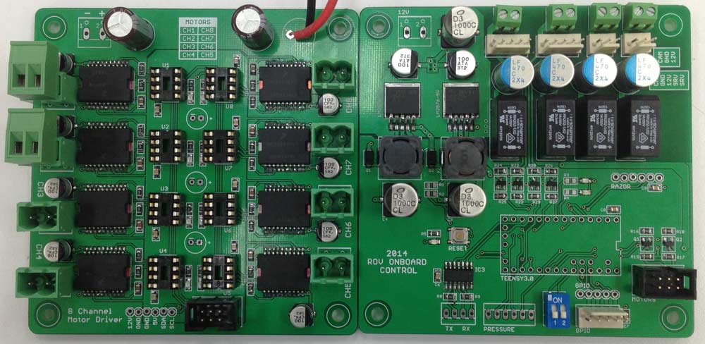
Motors are controlled with 5A MC33886 motor drivers. Each one is individually PWM driven with attiny85s, which also report faults over the I2C bus.
A MAX13432 handles the full-duplex differential comms.
Stackup
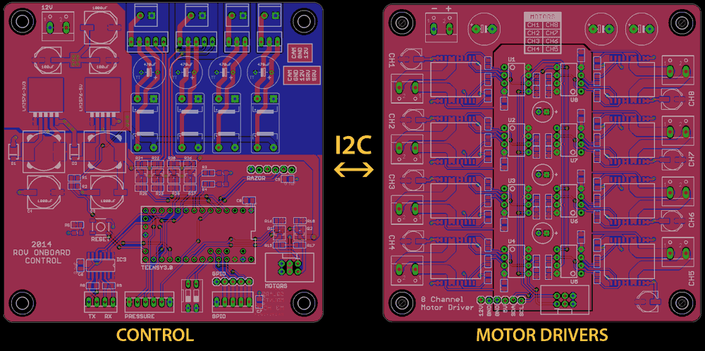
There are three layers inside the control box: primary control, motor driver, and video baluns. All of them are arranged in a 100x100mm grid, with standoffs stacking them up. Layers will be added as needed for sensors that were not planned.
Schematics
Generated from Eagle.