Repairing a Daktronics 7-Segment Scoreboard
January 4th, 2013
Projects
The pool at my school has an old-style daktronics LED scoreboard that looks like this:
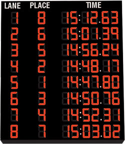
Most of the time the scoreboard is off, but there is an option for it to display the current time like a clock. The time is shown on the second row (in the picture it is at the 15:01.39 time), and over the years of constant operation, many of the leds on that row have reached EOL and died. It didn’t look like a hard fix so I asked the director to remove the digit modules and see if I can fix them.
The first thing anyone should do in this situation is to check the repair manual, so thats what I did. Hidden at the very end of the pdf was this:
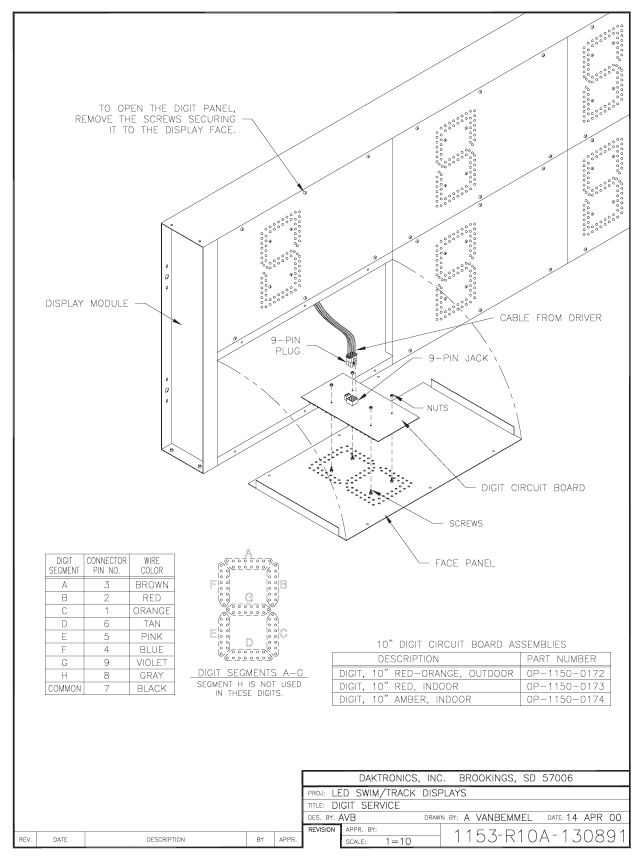
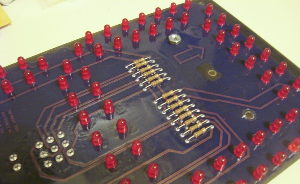
Not too helpful, but I can tell there are 14 LEDs per segment, and 98 per digit. The removed modules confirmed what the manual said. Curiously, each segment has two separate chains of seven LEDs (this likely because if one chain fails, an incorrect digit wont be displayed).
specifications
There are no published specifications for the modules so I probed around and came up with these:
- 12V input, common anode
- 9-pin molex square connectors
- 7 LEDs in series with a 1/2W 150-ohm resistor (I will call these chains)
- The stock LEDs have a Vf of about 1.55V (not quite sure how accurate this is)
process
The modules have a clear conformal coating on the front and back, which was a real pain to work with. The coating meant that the probes didnt make contact properly, so I had to scrape it off. Once I began soldering, the iron melted it away.
A comparison of the new LEDs and the old. The right segment has not been replaced in this photo.
I broke down replacing LEDs into five steps:
- Break off the old LEDs with pliers - the old ones were dead, so there is no point in keeping them
- Remove remaining LED leads from board
- Wick off the remaining solder still in the via
- Insert the new LED, solder one leg
- Position it so it is flush with the board, then solder the other leg and clip the leads
gallery
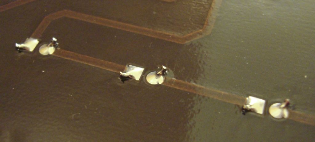
The leads are bent in the factory (presumably to hold it in place).
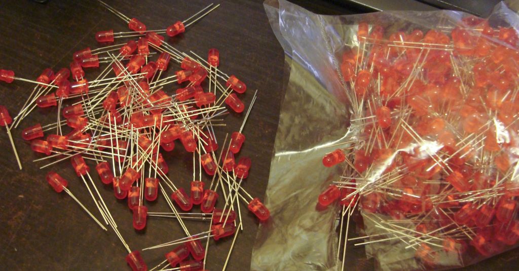
Bag of 600 5mm red LEDs. Bought from my local electronics store for $30.
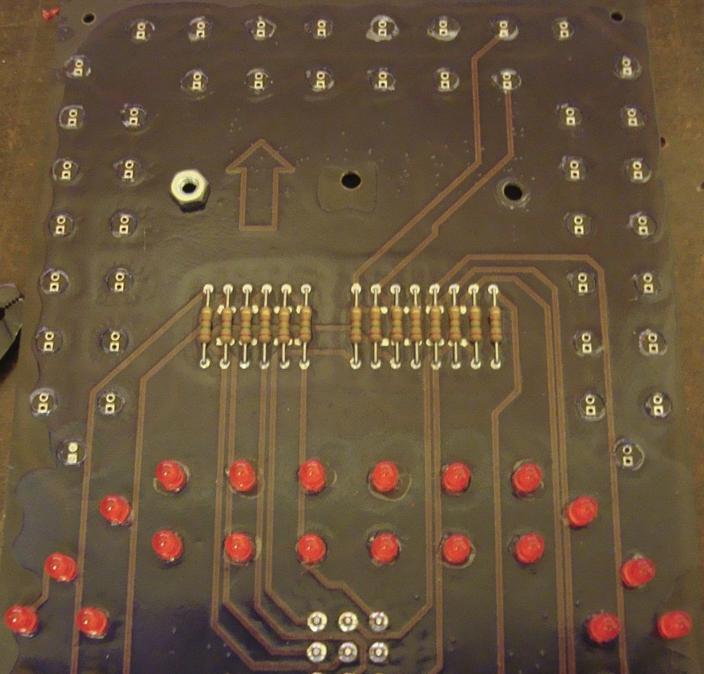
Front side of the board with half of the bulbs removed. The round bits surrounding each pad is the epoxy from the conformal coating.
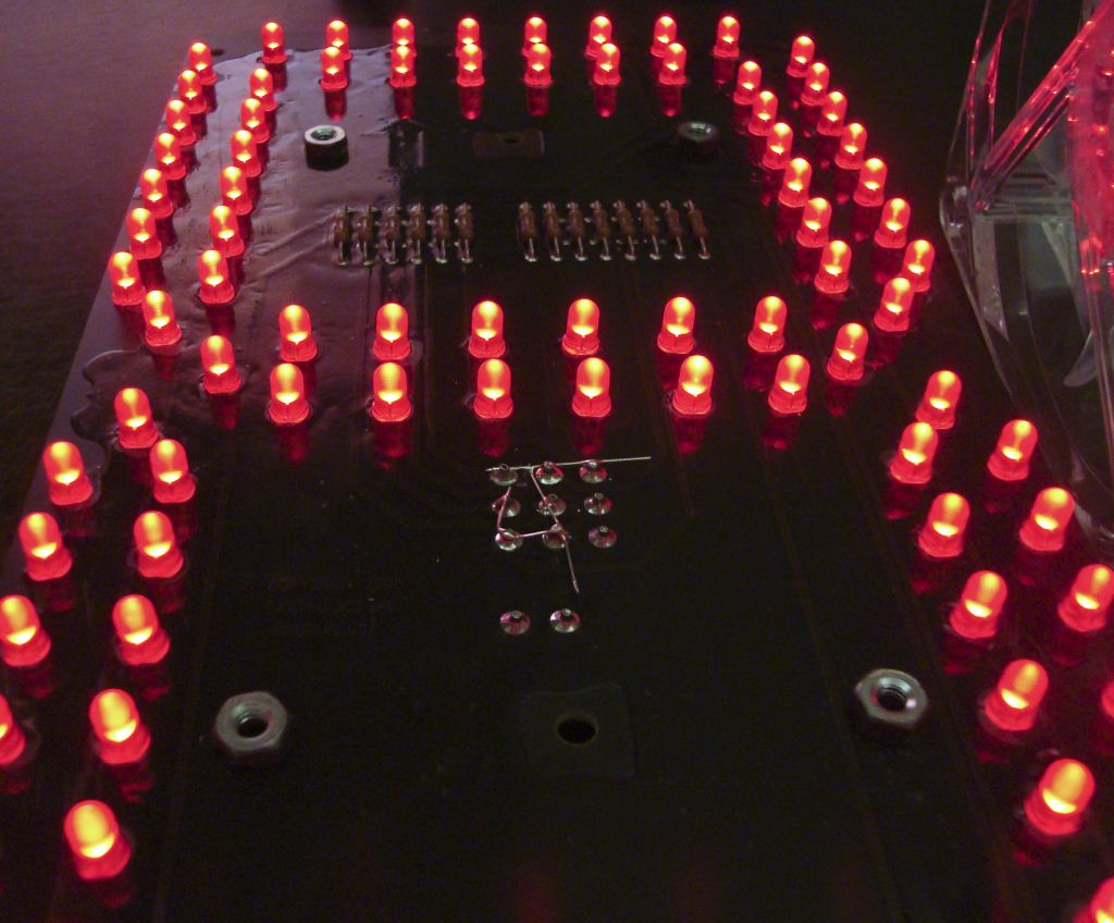
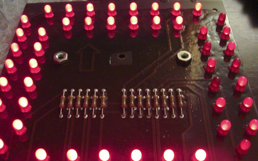
One of the six boards that were repaired. Red LEDs actually come in different wavelengths, and the one I bought were slightly more orange than the stock ones.