Reverse engineering a scoreboard data protocol (Nevco MPC-5)
March 3rd, 2017
Projects
I have decoded the Daktronics scoreboard signal in the past for a swim meet, but this time it’s a Nevco MPC-5 multipurpose controller for a basketball. Like the swim meet, the goal was to be able to get the clock & score data out of the controller. This was considerably more difficult to reverse engineer for several reasons:
- The Daktronics is standard RS232, the MPC-5 runs a non-standard signal
- The MPC-5 sends all scoreboard information over a single coaxial cable
- The clock rate is significantly higher. Daktronics is at 19200 baud (19.2 KHz), the MPC-5 at ~260 KHz
- I had less time with the actual controller to play around with
In this post I will outline the methods I used to reverse engineer the signal and extract the game clock, shot clock, home/away score signals.
Background research
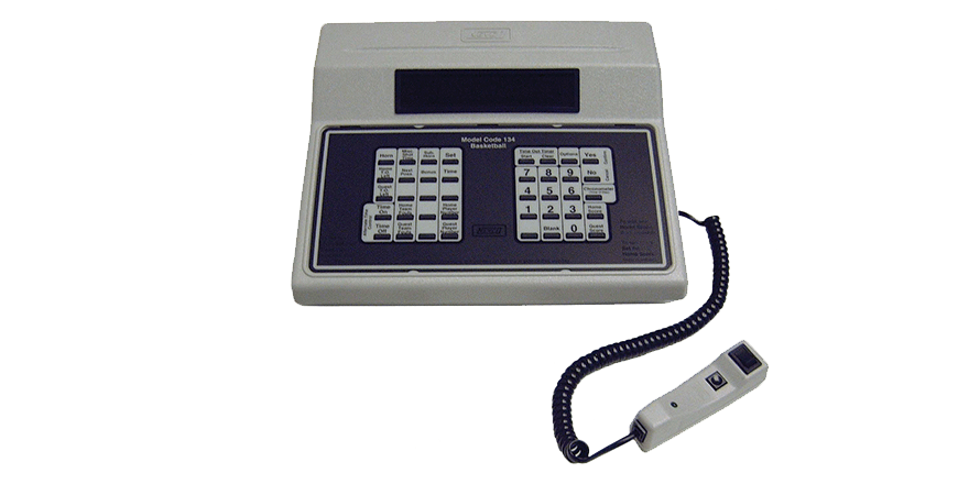
The Nevco MPC-5 has a BNC output and comes with a standard BNC cable to connect to the scoreboard. Some basic Googling for the model number and corresponding scoreboard model number didn’t give much valuable information about the signal specifications. The only useful information found was that the cable should be RG-58, which gives it a impedance of 50 ohms. Useful for the circuit design later.
G. Control cable where required shall be UL listed, 2-wire, type RG-58/U, coaxial cable, [1/4 inch] [6 mm] diameter.
Physical layer
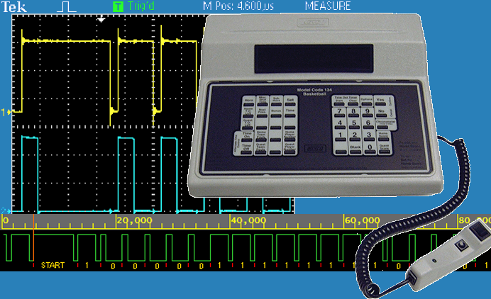
The raw signal from the NPC-5 on the oscilloscope looks like this: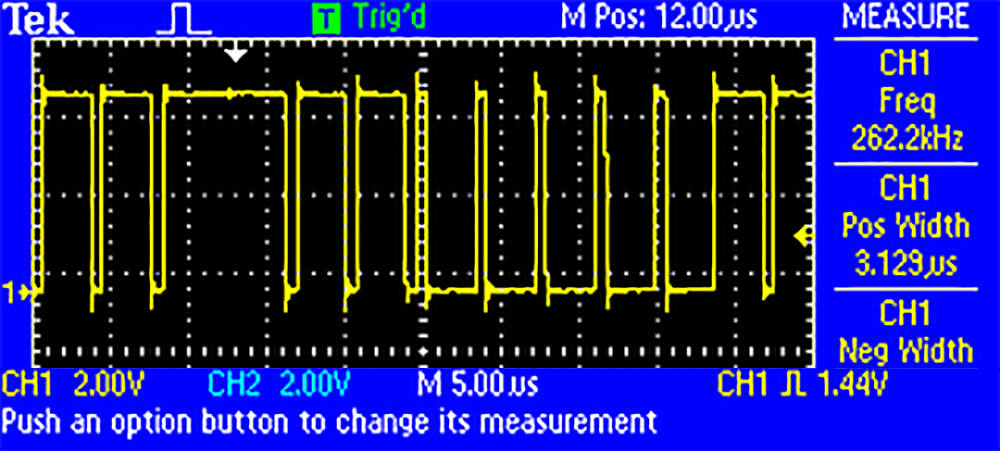
So the signal is ~5Vpp ~262KHz, which is a little off from the standard 256KHz for RS232. There also isn’t a stop bit. There aren’t many serial protocols at this frequency that run on coaxial cable, and the ones I have used before (DMX, RS232/485, CAN bus, I2C, SPI) do not match the signal or cabling, so some more research needed to be done.
After some research, it looks like this signal is a variation of the 1-Wire protocol, possibly inverted. Some more analysis with the logic analyzer: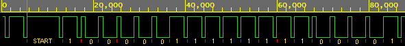
I have added annotations to where I deduced the bits are. I have made the assumption that all bits start on the rising-edge. 1-Wire specification says it starts on the falling-edge, but either way, the same bitstream can be read. With the logic analyzer, the following deductions can be made:
- Start bit - the start bit is a ~8 microsecond high pulse, followed by a ~0.7 microsecond low pulse
- 1 - a ~3.1 microsecond high pulse is followed by a ~0.7 microsecond low pulse
- 0 - a ~0.7 microsecond high pulse is followed by a ~3.1 microsecond low pulse
The ~3.8 microsecond pulse length gives the signal a ~262KHz data rate, disregarding the start bit. Total of 256 bits are sent (32 bytes) between start pulses.
Reading the signal
To read this non-standard signal into a microcontroller, I came up with a solution that uses the rising-edges of each bit followed by a delay as a trigger to read the signal. A 0-bit start with a ~0.7µs high pulse, so a reading of the signal ~1µs later will ensure that a proper reading of 0V is made. Along the same lines, a 1-bit starts with a ~3us high pulse, so a reading 1µs after the starting rising-edge will still have a reading of 5V.
A monostable multivibrator has the exact functionality required for this - when triggered by a rising-edge from the MPC-5, the multivibrator will output a high 5V for fixed 1µs, after which it returns to a low 0V. That falling-edge can be used as a trigger to read the MPC-5 signal.
Of course, nothing is this ideal in the real world, and after trying the 74LC123 (the standard 74-series multivibrator), I found that it was very difficult to accurately have a 1µs pulse required for triggering. Standard multivibrators aren’t really designed for 1MHz operation - this was confirmed by the datasheet:
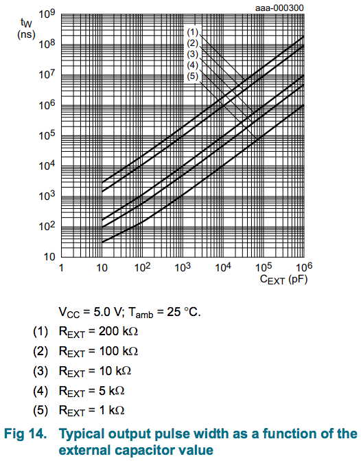
A output pulse of 1 microsecond requires a very small capacitance of ~80pF to ~800pF, and those are in very ideal conditions. Capacitors tolerances are very wide so a RC pair that is reproducible for a 1µs pulse is very difficult to find.
Microcontroller multivibrator
To have a reliable ~1 microsecond trigger delay, a ATTiny85 microcontroller (attiny85_multivibrator) with a interrupt triggered by the rising-edge was used. The input was the MPC-5 signal, and the two outputs were the trigger pulses, one for the data bits and one for the start bit. A naked ISR specified by ISR_NAKED had to be used to speed up the ISR. A custom prologue/epilogue in ASM was added.
Set up the interrupt triggered by a rising edge on the MPC-5 signal:
#if defined (__AVR_ATmega328__)
    EICRA |= (1 << ISC00); // Trigger on rising edge
    EICRA |= (1 << ISC01);
    EIMSK |= (1 << INT0);  // Enable INT0 interrupt vector

#elif defined (__AVR_ATtiny85__)
    MCUCR |= (1 << ISC00); // Trigger on rising edge
    MCUCR |= (1 << ISC01);
    GIMSK |= (1 << INT0);  // Enable INT0 interrupt vector

#endif
Interrupt handler for all data bits, outputting a signal to the CLOCK_PULSE pin (PORTB1):
ISR(INT0_vect, ISR_NAKED) {
    asm( // Standard ISR entry, minus "known zero" setup
        "push r0\n"
        "in r0, 0x3F\n"  // Save status
        "push r0" // Might not be needed
    );

    on(CLOCK_PULSE);
    __builtin_avr_delay_cycles(5);
    off(CLOCK_PULSE);

    asm( // low-overhead ISR exit...
        "pop r0\n"  // matches "might not be needed"
        "out 0x3f, r0\n"  // restore status
        "pop r0\n"  // restore r0
        "reti\n"
    );
}
A simpler section of code in the main loop detects a high-pulse exceeding ~5us, which means it is must be a start bit so therefore output a pulse to the START_BIT_PULSE pin (PORTB0).
while(1) {
    clocks = 0;

    // Detect start bit - 7µs pulse
    while(get(INT0_PIN)) {
        clocks++;

        if(clocks > 4) {
            if(enableInterrupt == 10) {
                on(START_BIT_PULSE); // Send start bit pulse
                out(CLOCK_PULSE); // Enable interrupt clock OUTPUT
                enableInterrupt = 0; // Reset counter
                __builtin_avr_delay_cycles(50);
                off(START_BIT_PULSE);

            } else {
                in(CLOCK_PULSE); // DISABLE interrupt clock OUTPUT
                enableInterrupt++;
            }

            break;
        }
    }
}
Note that with a 16MHz crystal clock, each cycle takes 62.5 nanoseconds, however with the added operations before and after __builtin_avr_delay_cycles() and ISR interruptions, the delay times were difficult to predict and were done through trial and error on the scope.
The resulting trigger signal from the ATTiny85 looks like this (for data bits), with the yellow the MPC-5 signal and the blue the ATTiny85 trigger signal:
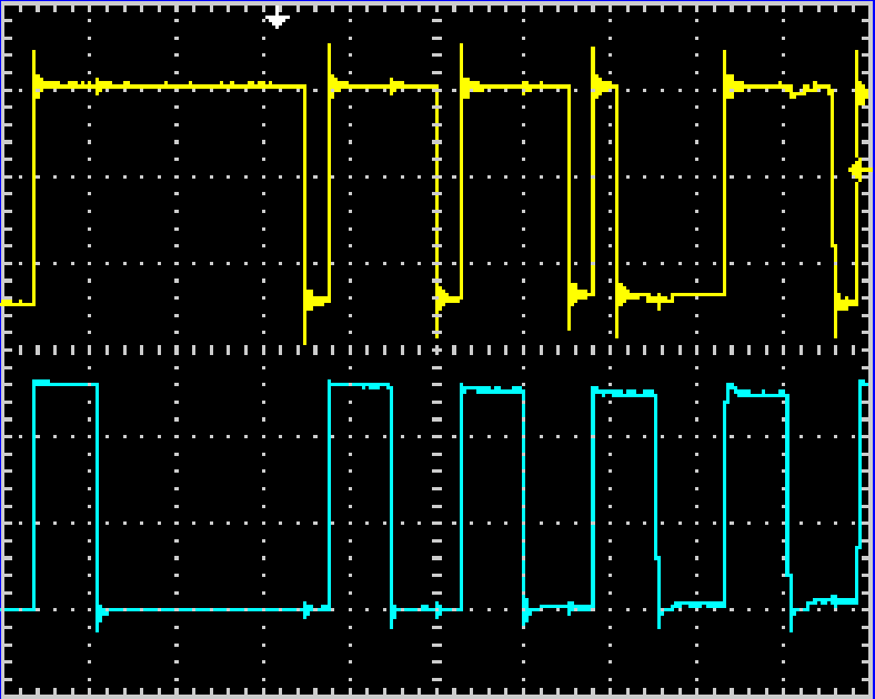
A reading of the MPC-5 (yellow) on every falling-edge of the trigger signal (blue) would yield the correct bit reading.
Master microcontroller
Now that a trigger edge can be generated with the ATTiny85, another microcontroller is responsible for reading the MPC-5 data on each falling-edge, shuffling it into bytes, then interpreting it to find the actual game clock and shot clock information on the scoreboard.
A Teensy was used for this, as it has a serial port, two interrupts available, and a interval timer. Its operation is similar to the ATTiny85, except that rather than outputting a trigger pulse, it reads the data, interprets it, then sends it along through TTL serial to a computer. Presumably, both microcontroller operations can be done on a single microcontroller, but this solution was easier for me to implement.
static volatile uint16_t bit_index = 0; // Increment this on each CLOCK ISR, reset on START ISR
static volatile uint8_t MPC5_bits[260]; // Holds bitstream for current packet

attachInterrupt(3, ISR_SERVICE_ROUTINE_DATA, RISING);
attachInterrupt(5, ISR_SERVICE_ROUTINE_START, RISING);

static void ISR_SERVICE_ROUTINE_START() {
    bit_index = 0; // Reset index to zero on each trigger edge
}

static void ISR_SERVICE_ROUTINE_DATA() {
    MPC5_bits[bit_index++] = digitalReadFast(6); // Read MPC-5 data from pin 6 into bitstream array
}
Getting the scoreboard data
To interpret the bitstream, a process of trial and error and observation was used. The full 256 bitstream was recorded with the controller set to a score of 0-0 and a clock time of 00:00. Then the controller was set to 0-1 and 00:00, then the complete bitstream recorded again. This goes on for every digit, so a complete set of bitstreams can be recorded.
To find the relevant bits for each scoreboard digit, I looked at the bits that were changing. Eventually, every single digit and its corresponding bit positions was mapped out:
| Digits | Bit Positions |
|---|---|
| Home team score | 150-153, 166-169 |
| Away team score | 6-9, 22-25 |
| Period | 54-57 |
| Shot clock | 238-240, 222-225 |
| Minutes | 118-121 |
| Seconds | 102-105, 86-89 |
Each digit is 4 bits, encoded with binary-coded-decimal. A simple function converts the BCD bits to a decimal value:
static uint8_t bcd_to_decimal(uint8_t bit1, uint8_t bit2, uint8_t bit3, uint8_t bit4) {
    uint8_t sum = 0;
    if(bit1) sum += 0b0001;
    if(bit2) sum += 0b0010;
    if(bit3) sum += 0b0100;
    if(bit4) sum += 0b1000;

    if(sum > 9) return 0;
    return sum;
}
Once all the digits are read from the bitstream, it is sent down the serial port every 100ms with the Teensy Metro library to a computer to generate the graphics.
Circuitry
Nothing special for the circuitry apart from a 5V-3.3V logic level converter and a 50 ohm termination. The MPC-5 signal is 5Vpp so it is shifted down to 3.3Vpp for the Teensy.
MPC-5 simulator
To test the decoder without having the actual MPC-5 controller, I coded a simple signal generator that reproduces the signal to specifications (5Vpp, ~260KHz, valid bitstream). This is in the atmega328_MPC_5_signal_generator folder.
Code
Code is published on GitHub at nevco-mpc5-signal-decoder.