Turing Alarm: A Mathematical Alarm Clock
April 12th, 2012
Projects
The arduino turing alarm is an adaptation of Nick Johnsons PIC-based one. At the time, I found that the PIC chip he used was a little too advanced for me, so I decided to use the Arduino microcontroller. All credits for the idea goes to Nick.
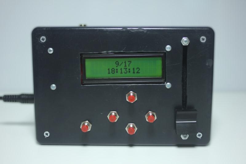
The turing alarm forces you to solve math problems when you wake up. If you get the math problem correct, the alarm stops, and if you don’t, you will have to solve another one. My version also includes a 12V light dimmer for the strip lights above my bed. A DS1307 real time clock (RTC) keeps track of the time and the menus are controlled with five buttons.
Code and circuit diagrams are on my github page. High resolution photos and other images are on my Picasa web album.
tools and materials
• Arduino board - I used the Uno board for testing and the Pro Mini for the final project
• DS1307 RTC - You can use the DIP version; I used the breakout from SparkFun
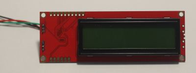
• SparkFun Serial LCD 16×2 - This is much easier to interface with than a parallel LCD
• Small 12mm buzzer (2.048 kHz)
• 5 SPST panel mount momentary switches
• 10k pull-down resistors - You will need seven of these
• 1 DC jack panel mount (two if you want light control)
• Project box - I used a 6 x 3 x 2″ project box from Radioshack
• Mounting screws and nuts (4-40 ½ inch) - Mount LCD and slide potentiometer
• 10K slide potentiometer - Only if you want light control
• N-channel MOSFET - Only if you want light control
RTC and LCD
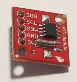
The RTC module uses the Wire I2C interface to communicate with the Arduino on A4 and A5. The data line (SDA) is on A4, and the clock line (SCL) is on A5. With the coin-cell battery on the module, the RTC can run for up to 17 years without an outside power source.
To set the time I used ladyada’s example code from her RTC library and tutorial. Her code sets the time using the local time on your computer. Make sure to uncomment this line of code:
RTC.adjust(DateTime(__DATE__, __TIME__));
A serial LCD is easier to use for this project because it only uses one data line (TX). For beginners like me SparkFun’s serial LCD is very easy to interface and use. Only three pins are needed, whereas a parallel LCD requires more than ten. To change a setting on the LCD like cursor position and backlight brightness, send a command line followed by the instruction, as outlined in the datasheet. For example, to clear the LCD you send this block:
Serial.print(0xFE, BYTE); // command line
Serial.print(0x01, BYTE); // instruction
For the turing alarm I used four commands: clear LCD, move to line 1, move to line 2, and set brightness. I wrote the ones used commonly into functions so it can be easily accessed. You can read more about the LCD and the protocol on the datasheet.
libraries and layout
I used three libraries for this project: the RTC library from ladyada, the Wire library for I2C, and the debounce (bounce) library from Thomas Fredericks. You can download them here:
RTClib: Ladyada’s github page
Bounce: Arduino.cc playground
Wire: Already included in IDE; go to Sketch > Import Library > Wire
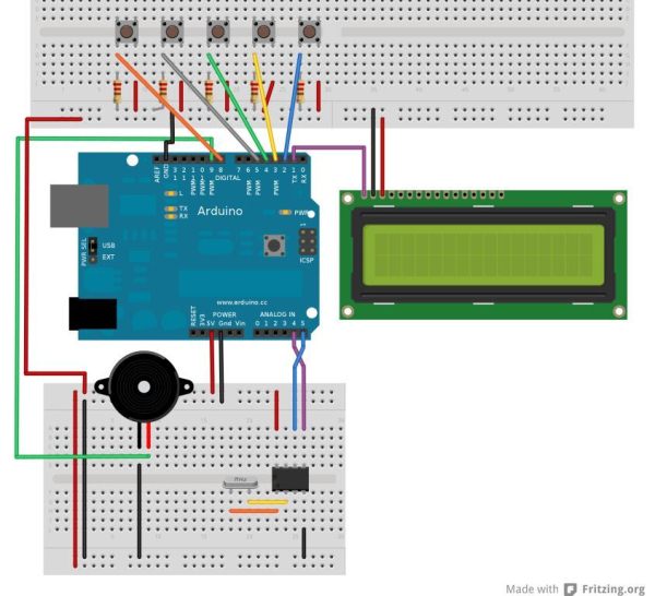
The turing alarm uses seven digital pins and two analog pins. The two analog pins are for I2C communication on the RTC and the digital pins are for the LCD, buttons, and the buzzer.
code
The code was written way back when I first learned the language. I realize that it is incredibly inefficient, but it worked at the time so I went with it. If I have time later, it will be rewritten and pushed on my github page.
The code uses seven different while loops for each menu. Within each of those while loops are if statements and display commands. The seven menus are:
• Main menu
• Choose set alarm, brightness, or IO monitor
• Set alarm time
• IO monitor
• Brightness control
• Alarm is on; turn off?
• Alarm math menu (this one is the menu when the alarm goes off)
When the the device is powered up, this function loops:
displayCurrentTime();
This function gets the time from the RTC and writes it to the LCD screen in a two-line configuration. The date is displayed centered on line 1 and the time is centered on line two.
When the OK button is pressed, the time is set and this line of code runs:
if (okDebounce == HIGH) {
    alarmSetting = 1;
    timePosition = 0;
    mathValOne = random(11, 20);
    mathValTwo = random(9, 15);
    mathValThree = random(20, 150);
    inputAnswer=(mathValOne*mathValTwo+mathValThree)-random(35,35);
    delay(20);
    MenuPosition = 7;
    delay(100);
    clearLCD();
    delay(500);
}
alarmSetting stores whether the alarm is on or off with a boolean variable: 1 for on, and 0 for off. This is used in other parts of the code to check if the alarm is on or not.
timePosition is used to store which time value is being changed (second, minute or time). This resets it to 0, or second. (0 for second, 1 for minute, and 2 for hour).
The next three lines of code determines the math problem. It picks a random value between the values shown based on a seed from randomSeed(analogRead(2)) in the setup.
inputAnswer stores what the user inputs as an answer. The line of code shown simply sets the variable to a value that is close to the actual answer.
The next five lines of code clears the LCD and changes the menu.
After the alarm time is set, the loop constantly checks if the alarm time is equal to the real time with this line of code:
if(alarmSetting == 1 && alarmSecond == now.second() && alarmMinute == now.minute() && alarmHour == now.hour())
The problem with this line is that it doesn’t check for date, so the alarm goes off within 24 hours. It is adequate for myself, but if you need to set alarms for more than a day later add a set date function.
When the alarm goes off, this block of code runs:
alarmNoiseOn();
realAnswer = mathValOne * mathValTwo + mathValThree;
moveLineOne();
Serial.print(” Hello!”);      // wakeup message

moveLineTwo();
Serial.print(mathValOne);
Serial.print(“*”);
Serial.print(mathValTwo);
Serial.print(“+”);
Serial.print(mathValThree);
Serial.print(” = “);
Serial.print(inputAnswer);
Serial.print(” ?”);
delay(100);

if(debounceIncrease == HIGH) {
    inputAnswer++;
}

if(debounceDecrease == HIGH) {
    inputAnswer–;
}
AlarmNoise on is a tone function that beeps the buzzer in a familiar ‘alarm’ pattern. realAnswer stores the actual answer that will turn off the alarm. The last two functions check if the up or down buttons have been pressed.
When the OK button is pressed, the code checks if the input answer is equal to the actual answer. If it is, noTone is called (turns off the buzzer) and all the variables are reset. A wakeup message is displayed for five seconds then the alarm returns to the main time menu.
delay(500);
noTone(9);
clearLCD();
alarmSetting = 0;
moveLineOne();
Serial.print(” Good Morning!”);
delay(5000);
MenuPosition = 0;
mathValOne = 0;
mathValTwo = 0;
mathValThree = 0;
alarmSecond = 0;
alarmMinute = 0;
alarmHour = 0;
If the input answer is not equal to the actual answer, then the math values are reset to a different random value, giving the user another problem to solve.
pcb
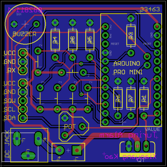
I also drew a PCB design in EagleCAD for those who are too lazy to solder on a perfboard. The double-sided one is very densely populated, and is meant for a board-house to make. All the parts are squeezed in to a 5cm square to keep the price low ($9.90 at Seeed). There is also a schematic that comes with the PCB layout.
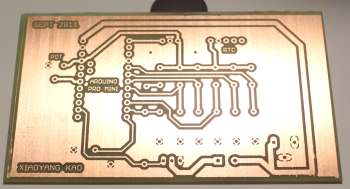
If you would rather etch your own circuit board, use the single layer version that is much bigger (6*10 cm) and easier to etch. The picture is of the board I etched. Note that there is one jumper that you will need to connect with hookup wire; it is located at the top center of the board.
mounting parts
All of the parts except for the buttons and the jack are mounted with 4-40 screws and nuts. The buttons and jacks are already threaded with a nut, so a 1/4 inch hole is all you need. For the 4-40 screws, I used a ~2.5 mm hole.
The LCD has four mounting holes, one on each corner. The LCD itself does not sit flush with the board, so you will need to use spacers on each hole. I found that two 4-40 nuts work well as spacers. You will need 12 nuts in total for the LCD: 8 for spacing, and 4 for securing.
The slide potentiometer is a little tricky because many spacers are needed. When the knob is attached, it sits much higher than where the mounting holes are. Just keep on adding spacers until the knob sits relatively flush on the box.
Mark where to drill the holes and mount the components. If you need measurements, open the CorelDRAW file and use the ruler tool. You can also submit this file to a laser-cutting service (Pololu, for example) and have it laser etched and cut.
troubleshooting
The serial LCD is displaying a black line/random text/nothing.
I got this problem very often when working with the LCD. Most of the time the problem fixes itself when you cycle the power or adjust the contrast. To prevent this from happening again, remove the serial wire from the Arduino when uploading code. Sometimes it sends a random serial message that could change the settings on the LCD or display random text. If cycling power does not fix the problem, upload and run Reset_Serial_LCD.pde attached below.
The time stays at 00:00:00 or doesn’t change.
Sometimes the RTC stops itself when debugging. Rerun the set-time sketch and you should be fine.