Controlling LED Matrices with the MBI5026 Driver
May 17th, 2012
Sandbox
Matrices are one of many interesting applications for LEDs. When multiple matrices are linked together into a ‘display’, scrolling text and even images could be projected.
In a regular single-color 8x8 matrix, 64 LEDs are arranged in a square with eight on each side. Multicolor red-green-blue matrices are also available, but the complexity increases dramatically because there are three times the number of LEDs.
If you think about it, every LED in the 8x8 matrix would need a cathode and anode to control (a total of 128 pins), right? It makes sense if you think about 64 of them in a line. In a matrix, however, the LEDs are in rows and columns. By connecting all the anodes in each row and all the cathodes in each column, every single LED could be controlled with 16 pins. This introduces another problem: it is not possible to control individual LEDs separately at the same time. To get around this, I will use the technique of multiplexing.
multiplexing
Multiplexing is a common technique used to control large LED matrices and displays. Multiplexed displays only have a single row on at any time. When a row is on, the driver IC tells the columns which LEDs in that row to light up. The cycle repeats for every row in the system one after the other, forming a image to the human eye. Depending on the microcontroller, the speed at which it repeats ranges from microseconds to milliseconds. From my experimenting, anything above a refresh rate of 30ms for a regular 8x8 display (~3.5ms between row) becomes noticeable to the eye, and flickering will occur.
persistence of vision

Early movies used persistence-of-vision to animate objects.
An interesting thing about the human eye is that it cannot detect changes faster than around 40 milliseconds. This oversimplified example explains it pretty well: the AC power going into the lights in your house runs at 50 or 60 hertz, depending on where you are in the world. With a high-speed camera, you can actually see the filament flashing on and off at that frequency. Your eyes, however, cannot see that fast, so it interprets it as a continuous light source. Multiplexing takes advantage of this phenomenon. This is also the underlying principle behind pulse-width modulation.
Now that i’m done with the theory of operation, we can get to picking parts and drawing circuits. My final display will have 12 matrices in a 4x3 arrangement, so I picked parts based on that. The 16-bit parts can still be used to control a single matrix, however.
components
74HC154
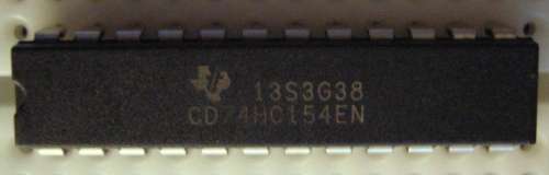
Since my eventual 4x3 display will have 24 rows of 36 LEDs, I picked this 16-bit multiplexer to control the rows. Don’t confuse multiplexer and multiplexing: the 74HC154 multiplexer turns on a specified output pin out of a bank of 16 based on a 4-bit binary input (A0-A3), whereas multiplexing is the technique used to control all the LEDs. For example, if 0101 is sent to the four binary inputs (A0-A3), the fifth output pin would be enabled because 0101 is 5 in decimal form. The 74HC154 is ‘active-low’, meaning the specified output pin goes LOW and the rest HIGH when assigned by the 4-bit input. This sounds counterintuitive, but it guards against all the rows turning on and killing the power supply if the multiplexer fails. Nonetheless, it is not really relevant in our case because we will be using PNP transistors. Two of these will allow control of up to 32 rows.
2N5401 PNP transistor
Speaking of transistors, I will be using 2N5401s to supply power to the rows. The 74HC154 is not meant for supplying large amounts of current, which is what we need to power all the rows. Why not the more common 2N3906? The 2N3906 has a maximum current rating of 200mA, whereas the 5401 can handle 600mA. My display will have 36 LEDs per row, and 200mA is not enough to power all of them at full brightness. 24 transistors will be needed; one for each row. Every one of these will be connected to separate output pins on the multiplexer. Since these are PNP transistors, they will be OFF when there is current at the base pin. They will only turn ON and allow current to flow through the row of LEDs when there is NO current at the base. The 74HC154 is active LOW, so the PNP transistors will only turn ON when assigned through the 4-bit input.
MBI5026 16-bit Constant-current sink LED driver
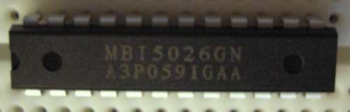
The LED driver is the most important part of controlling the display. The MBI5026 is a current-sink, meaning it allows current to pass to ground. I picked the MBI5026 to drive the columns for three reasons: it has 16 output pins, there is a constant current feature, and because it is readily available where I live. The constant-current feature means that a current-limiting resistor for each LED is not required at all. The current for all the output pins is set by an external resistor. The MBI5026 acts like a shift-register: data is shifted into three data pins, and multiple chips can be chained together for more output lines. A practically unlimited amount of pins can be controlled with only three inputs. An example with one of these: 0000000000000001, a 16-bit binary number, is shifted into the chip. All outputs will not allow current to flow except the first pin, so the first LED will be lit. The Arduino shiftOut() function doesn’t support 16-bit shift registers, so two separate bytes of data (one for 8-15, one for 0-7) will be sent before the data is latched. With two of them I can control all 32 columns of the display.
With these three primary components, all rows can be multiplexed. A row-transistor is turned on with the 74HC154 (not necessarily lit), allowing current to flow. The MBI5026 picks which LEDs in the row to turn on, completing the circuit and lighting the specified LED.
For now I will only use one 8x8 matrix because I don’t have more breadboards available :).
assembly
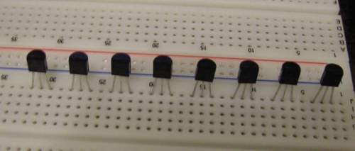
Eight 2N5401s: one for each row in the matrix. The three pins are as follows from left to right: emitter, base, collector.
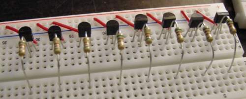
510 ohm base current resistors for each transistor. The collectors of each transistor are tied to the supply voltage.
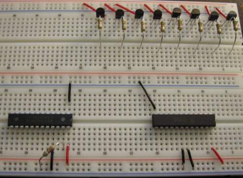
MBI5026, 74HC154 with supporting circuitry. The resistor is used to set the constant current level in the driver.
The outputs on the multiplexer tied to each transistor.
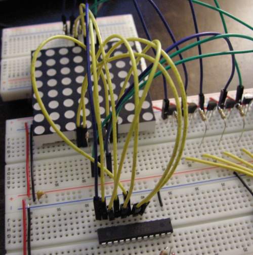
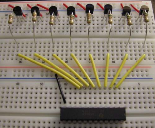
The LED driver is connected (yellow and one blue) to the column pins of the matrix, and the multiplexer to the rows (green and blue).
The LED driver is connected to pins 2-4, and the multiplexer to pins 9-13. In my case, pin 2 is the data pin, pin 3 is the clock, and pin 4 is the latch.
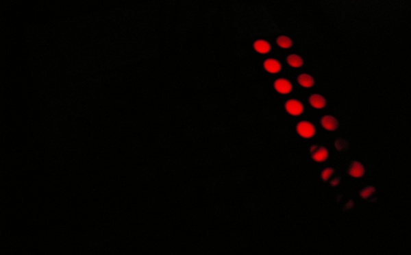
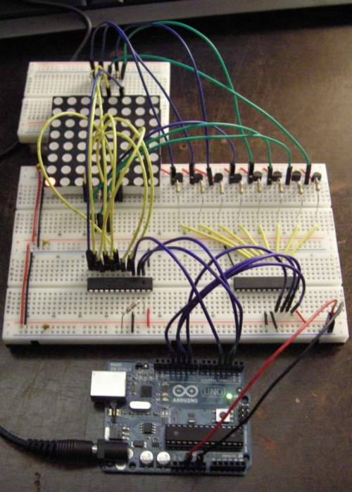
This photo illustrates the multiplexing effect very well. The photo was taken with an exposure of 1/1000s, equivalent to the refresh rate I set the display to. When I took the photo, to the eye it looked like the entire display was on at the same time. However, the multiplexer was actually lighting each row for 1ms, then turning it off and lighting the next one. The human eye cannot detect motion this fast, but the camera did.
Full Picasa web album with more detailed photos here. Code is available on my github page.